Create Composable Overlays (hw)
This tutorial will show how to create a composable overlay from scratch using standard IP from the Vivado IP catalog. In particular, we will use
Create a Vivado project
Creating a new composable overlay starts like any other design hardware design for PYNQ, if you are not familiar with this process check out Tutorial: Creating a hardware design for PYNQ
In this case we will target the Kria KV260 Vision AI Starter Kit, note that we will use Vivado 2020.2.2 (first release that supports the Kria KV260 Vision AI Starter Kit)
Create a New Project
Click Next > in the first window
Set Project name: to
composable_filter(a); select the Project location: that is more appropriate for you (b); click Next > (c)Set the Project Type to RTL Project (d); check Do not specify sources at this time (e); click Next > (f)
Set the Default Part, click on Boards (g); then select Kria KV260 Vision AI Started Kit (h); click Next > (i)
Click Finish (j) on the Project Summary window
The animated GIF below shows these steps
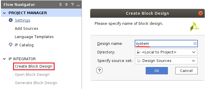
Create a Block Design
Under IP INTEGRATOR, click on create Block Design
Set system as design name
Add Processing System
As we will be moving data from the ARM processor to the Programmable Logic add the Processing System (PS).
In the Diagram tab (a) click the + symbol to add an IP (b)
Search for zynq and select Zynq Ultrascale+ MPSoC (c)
Run Block Automation (d) to configure the PS block with the default settings for the Kria KV260 Vision AI Started Kit
Check All Automation (1 out of 1 selected) (e) and then click OK (f), the block is now configured (g)
Configure the PS
Double click on the Processing System block, or right click on it and select
Customize Block...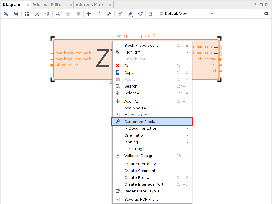
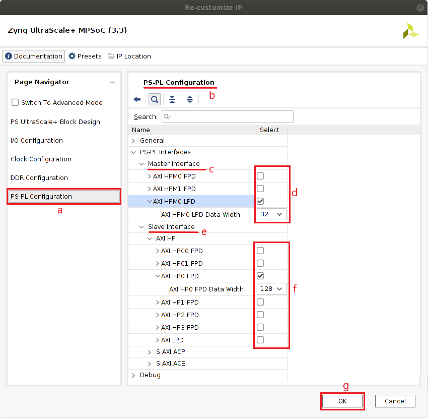
In the Page Navigator, select the PS-PL Configuration (a)
In the
PS-PL Configurationpane (b), expandPS-PL Interfaces > Master Interfaces(c)Uncheck
AXI HPM0 FPDandAXI HPM1 FPDthen checkAXI HPM0 LPDand make sure that theAXI HPM0 LPD Data Widthis set to 32 (d)In the
PS-PL Configurationpane expandPS-PL Interfaces > Slave Interfaces(e)Check
AXI HP0 FPDand make sure that theAXI HP0 FPD Data Widthis set to 128 (f)Click OK (g)
Add Direct Memory Access (DMA)
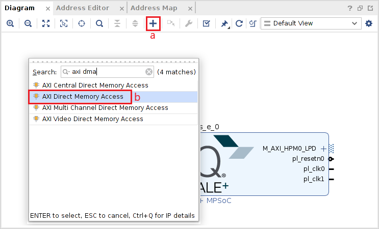
Click the
+button to add a new IP (a)Search for AXI Direct Memory Access (b)
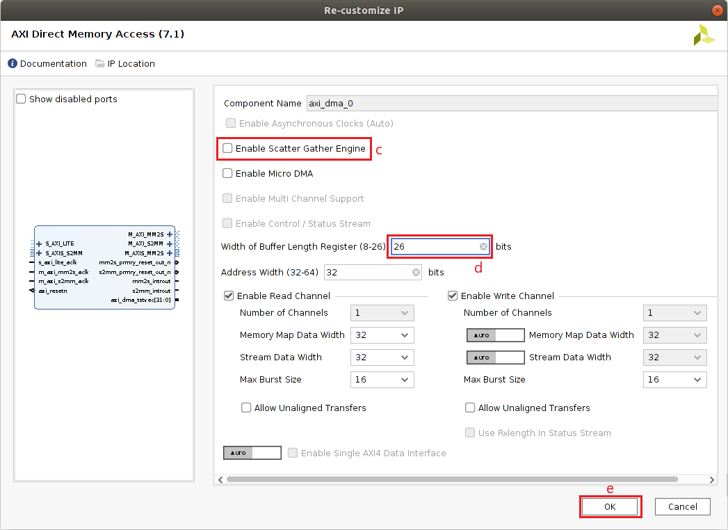
Double click on the AXI Direct Memory Access to configure the block
Uncheck Enable Scatter Gather Engine (c)
Set the Width of Buffer Length Register to 26 (d)
Click OK (e)
Modify the name of the DMA by selecting the block and then on the Block Properties window, on the left hand side, change the name to
axi_dma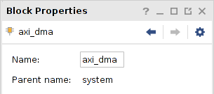
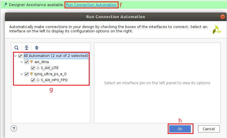
Click Run Connection Automation (f)
Check All Automation (2 out of 2 selected) (g) and then click OK (h)
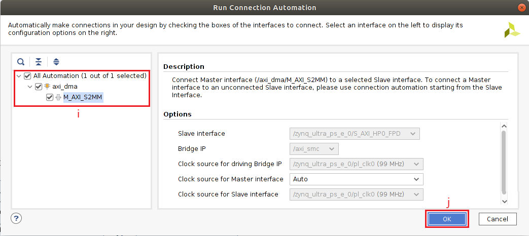
Click Run Connection Automation again
Check All Automation (1 out of 1 selected) (i) and then click OK (j)
The result is shown below
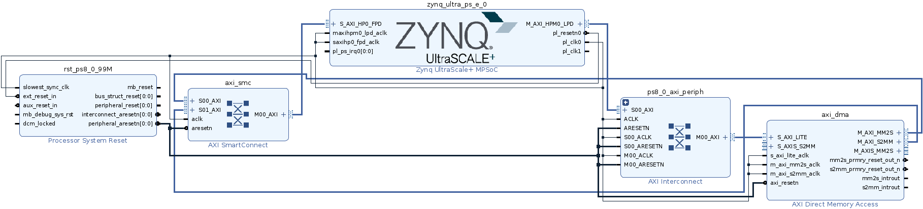
For a comprehensive tutorial about the DMA block read this blog.
Add Interrupt Controller
As you may have noticed, the AXI Direct Memory Access has two interrupts,
mm2s_introut and s2mm_introut. We need to connect these to the PS.
pynq support multiple interrupts via an AXI Interrupt Controller.
For more information check out the documentation
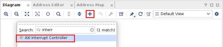
Click the + button
Search for AXI Interrupt Controller
Rename the block to
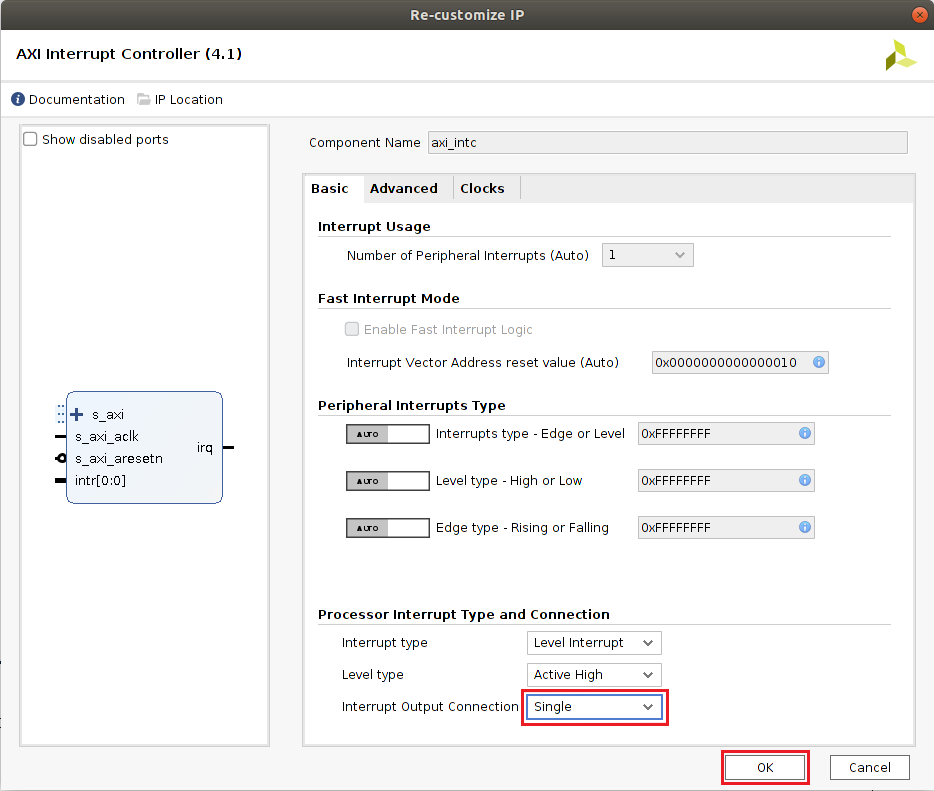
axi_intcDouble click on the AXI Interrupt Controller module to configure it
Change Interrupt Output Connection to Single and click OK
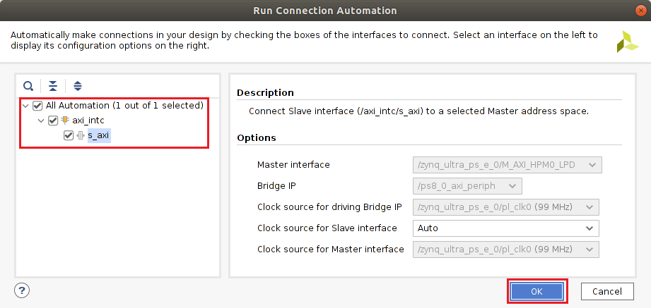
Click Run Connection Automation
Check All Automation (1 out of 1 selected) and then click OK
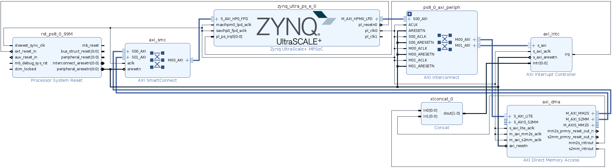
Wire the
axi_intc/irqpin to thezynq_ultra_ps_e_0/pl_ps_irq0pinAdd a
ConcatIP. By default this IP has to inputs and one output, this is exactly what we needWire the
axi_dma/mm2s_introutpin to any of thexlconcat_0input pins, do the same for theaxi_dma/s2mm_introutpinWire the
xlconcat_0/doutpin to theaxi_intc/intrpin
The result is shown below
Make the Overlay Composable
With the basic infrastructure in place, it is high time we made this overlay composable.
There are two key characteristics of a composable overlay 1) it uses at least one AXI4-Stream Switch – configured to use control register routing– and 2) wrap the composable logic into a hierarchy. The instructions below describe the steps to accomplish this.
Add the AXI4-Stream Switch
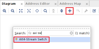
Click the + button to add a new IP
Search for the AXI4-Stream Switch
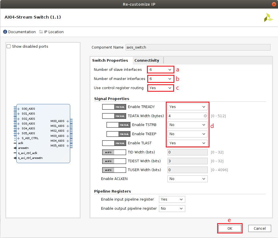
Double click on the AXI4-Stream Switch module to configure it
Set the Number of subordinate interfaces to 6 (a)
Set the Number of manager interfaces to 6 (b)
Set Use control register routing to Yes (c)
In the Signal Properties section, enable TREADY and TLAST, disable TSTRB and TKEEP, set TDATA Width (bytes) to 4 (d)
Click OK (e)
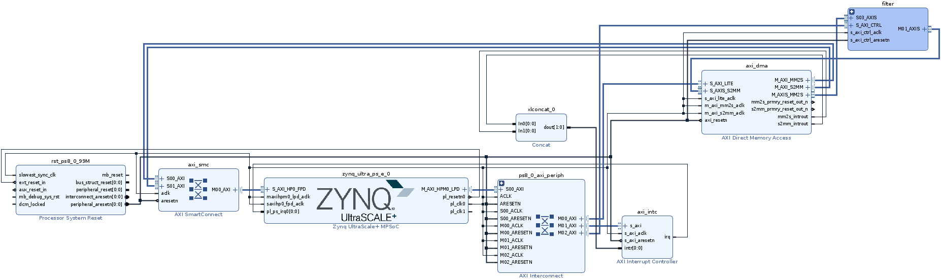
Connect the
axi_dma/M_AXIS_MM2Sinterface to theaxis_switch_0/S03_AXISinterfaceConnect the
axis_switch_0/M01_AXISinterface to the interfaceaxi_dma/S_AXIS_S2MMNote that the connections to the AXI4-Stream Switch are arbitrary, you can change these connections if you wish
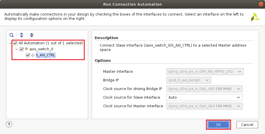
Click Run Connection Automation
Check All Automation (1 out of 1 selected) and then click OK
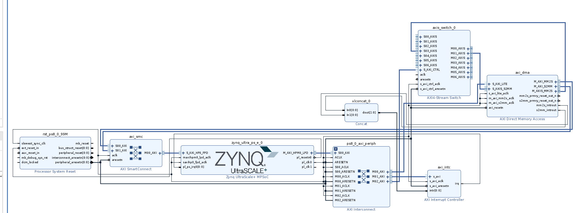
The result is shown below
Create Composable Hierarchy
Right click on the AXI4-Stream Switch and then click on Create a Hierarchy…
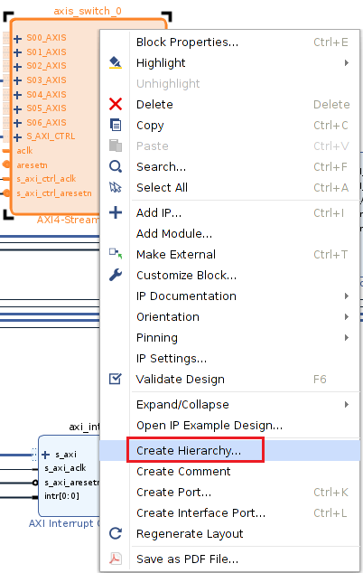
Use Cell name: filter
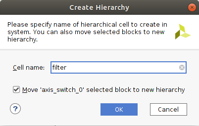
The result is shown below
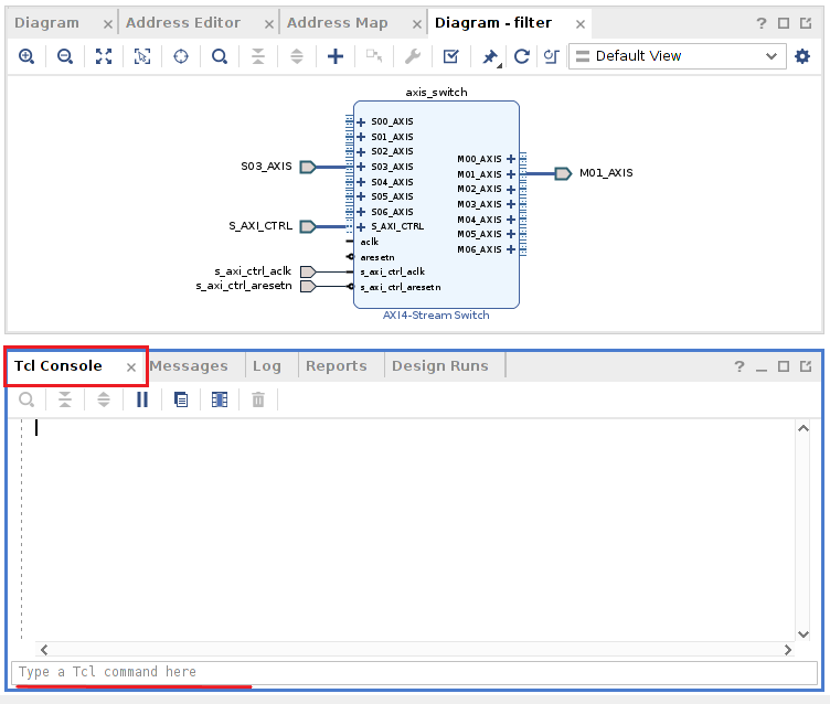
Double click on the hierarchy to inspect it.
Add Filters
So far, we have added the AXI4-Stream Switch and created the hierarchy. Let’s now add the IP blocks that will be part of our composable scope. For this, we will use the standard Xilinx IP to implement Finite Impulse Response (FIR) filters. If you are not familiar with FIR filters, all you need to know is that FIR filters are a way to remove unwanted components from a signal. In this tutorial we are going to instantiate four FIR filters: 1) low pass filter, 2) high pass filter, 3) pass band filter and 4) stop band filters. The configuration for these filters can be found in the appendix section.
To make this step easier we will use TCL commands. To execute these commands use the TCL console.
Copy and paste the following TCL commands on the TCL console.
set_property name axis_switch [get_bd_cells filter/axis_switch_0]
set filter_names "fir_lowpass fir_highpass fir_bandpass fir_stopband"
foreach fir ${filter_names} {
set obj [create_bd_cell -type ip -vlnv xilinx.com:ip:fir_compiler:7.2 "filter/${fir}"]
set_property -dict [ list \
CONFIG.Coefficient_Fractional_Bits {0} \
CONFIG.Coefficient_Reload {false} \
CONFIG.Coefficient_Sets {1} \
CONFIG.Coefficient_Sign {Signed} \
CONFIG.Coefficient_Structure {Inferred} \
CONFIG.Coefficient_Width {16} \
CONFIG.DATA_Has_TLAST {Packet_Framing} \
CONFIG.Data_Sign {Signed} \
CONFIG.Data_Width {32} \
CONFIG.M_DATA_Has_TREADY {true} \
CONFIG.Output_Rounding_Mode {Truncate_LSBs} \
CONFIG.Output_Width {32} \
CONFIG.Quantization {Integer_Coefficients} \
] $obj
}
set_property -dict [ list CONFIG.CoefficientVector {-133, -375, -356, -559, -643, -731, -731, -650, -458, -153, 263, 772, 1348, 1949, 2532, 3048, 3453, 3712, 3800, 3712, 3453, 3048, 2532, 1949, 1348, 772, 263, -153, -458, -650, -731, -731, -643, -559, -356, -375, -133}] [get_bd_cells filter/fir_lowpass]
set_property -dict [ list CONFIG.CoefficientVector {1136, -1197, -580, -33, 438, 658, 461, -116, -762, -1015, -565, 480, 1532, 1774, 604, -1953, -5154, -7805, 23932, -7805, -5154, -1953, 604, 1774, 1532, 480, -565, -1015, -762, -116, 461, 658, 438, -33, -580, -1197, 1136}] [get_bd_cells filter/fir_highpass]
set_property -dict [ list CONFIG.CoefficientVector {195, 42, -82, -129, -41, -6, -269, -705, -710, 234, 1758, 2526, 1313, -1585, -4106, -3949, -708, 3427, 5298, 3427, -708, -3949, -4106, -1585, 1313, 2526, 1758, 234, -710, -705, -269, -6, -41, -129, -82, 42, 195}] [get_bd_cells filter/fir_bandpass]
set_property -dict [ list CONFIG.CoefficientVector {-1705, 2484, 232, -657, -484, 337, 1239, 1622, 1243, 449, 58, 737, 2347, 3809, 3706, 1322, -2668, -6410, 24833, -6410, -2668, 1322, 3706, 3809, 2347, 737, 58, 449, 1243, 1622, 1239, 337, -484, -657, 232, 2484, -1705}] [get_bd_cells filter/fir_stopband]
set axis_data_fifo [ create_bd_cell -type ip -vlnv xilinx.com:ip:axis_data_fifo:2.0 filter/axis_data_fifo ]
set_property -dict [ list CONFIG.HAS_TKEEP {0} CONFIG.HAS_TLAST {1} CONFIG.HAS_TSTRB {0} CONFIG.TDATA_NUM_BYTES {4} ] $axis_data_fifo
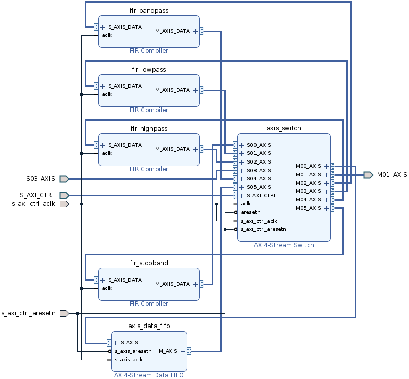
connect_bd_net [get_bd_pins filter/s_axi_ctrl_aclk] [get_bd_pins filter/axis_data_fifo/s_axis_aclk] [get_bd_pins filter/fir_bandpass/aclk] [get_bd_pins filter/fir_highpass/aclk] [get_bd_pins filter/fir_lowpass/aclk] [get_bd_pins filter/fir_stopband/aclk] [get_bd_pins filter/axis_switch/aclk]
connect_bd_net [get_bd_pins filter/s_axi_ctrl_aresetn] [get_bd_pins filter/axis_data_fifo/s_axis_aresetn] [get_bd_pins filter/axis_switch/aresetn]
Four FIR compilers and one FIFO were added to the hierarchy, note that the manager and subordinates of these blocks are not connected. You can connect the managers and subordinates of these IP to any manager or subordinate of the AXI4-Stream Switch, for instance as shown below.
Generate Bitstream
Now that our composable overlay is ready, let’s generate the bitstream.
Save Block Design by clicking on File > Save Block Design or CTRL + S
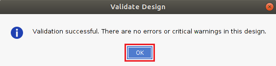
Validate the Design by clicking on Tools > Validate Design or F6 or click this button

Click OK on the pop up
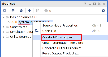
Generate the HDL wrapper, on the Sources window right clock on system and then select Create HDL Wrapper…
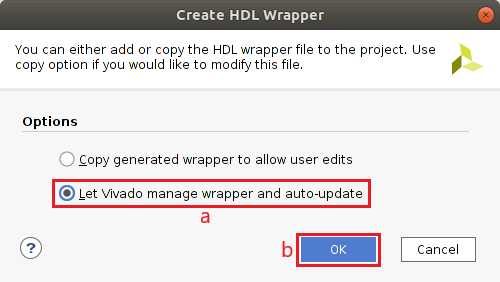
In the Create HDL Wrapper window select Let Vivado manage wrapper and auto-update (a) then click OK (b)
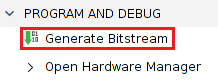
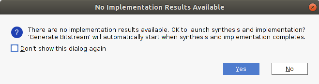
In the PROJECT MANAGER pane click Generate Bitstream
Click Yes to launch synthesis and implementation
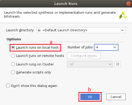
Select Launch runs on local host (a) then click OK (b)
Default Path
In a composable overlay, a default path specifies the nodes that are source
and sink in a design, this is consumer and producer. These default paths are
annotated with the keyword [default] in the c_dict. In this tutorial
the DMA connections define our default path. We will save information in a
file with the same basename as the overlay plus _paths in this case
fir_paths.json. This way the AXI4-Stream Switch gets automatically configured
at the initialization.
{
    "filter": {
        "ps": {
            "ci": {
                        "port": 3,
                        "Description": "Stream In"
                },
            "pi": {
                        "port": 1,
                        "Description": "Stream Out"
            }
        }
    }
}
Get Composable overlay files
Copy the overlay files, both *.bit and *.hwh from the project and then move
them to the Kria KV260 Vision AI Starter Kit, along with the default path file.
After the bitstream is generated, run the following commands in the TCL console to copy the overlay files to root directory.
set prj_path [get_property DIRECTORY [current_project]]
exec cp ${prj_path}/composable_filter.runs/impl_1/system_wrapper.bit fir.bit
exec cp ${prj_path}/composable_filter.gen/sources_1/bd/system/hw_handoff/system.hwh fir.hwh
Get composable overlay on the board
Finally, get the composable overlay files onto the board. You need to copy
fir.bit
fir.hwh
fir_paths.json
tutorial.ipynb
These files can be found here
This step assumes that you have PYNQ up and running on the Kria KV260 Vision AI Starter Kit. if this is not the case, follow the these instructions.
You can use scp or WinSCP to copy the files. However, the most convenient way is to directly drag and drop them from Jupyter Lab
Conclusion
This tutorial shows how to create a composable overlay from scratch using standard IP from the Vivado catalog. The composable overlay methodology it is not much different from the traditional overlay methodology. To create a composable overlay, you only need an AXI4-Stream Switch and a hierarchy to wrap the composable overlay. What is more, the capabilities of a composable overlay can be highly enhanced with DFX, however the DFX technology is outside the scope of this tutorial.
In the second part of this tutorial, Jupyter Notebook. We will explore our composable overlay directly from the KV260, and you will learn how to use it. You will notice that the Python API abstracts away the intricacies of the underlying hardware while providing maximum flexibility.
Appendix
FIR Compiler Configuration
These filters were generated with t-filter.engineerjs.com
The Sampling Frequency (fs) is 44100 Hz for the filters and all the FIR filters are implemented using 37 taps.
Low Pass Filter
From |
To |
Gain |
ripple/attenuation |
|---|---|---|---|
0 Hz |
2,000 Hz |
1 |
5 dB |
3,500Hz |
22,050 Hz |
0 |
-40 dB |
High Pass Filter
From |
To |
Gain |
ripple/attenuation |
|---|---|---|---|
0 Hz |
5,000 Hz |
0 |
-40 dB |
6,500Hz |
22,050 Hz |
1 |
3 dB |
Band Pass Filter
From |
To |
Gain |
ripple/attenuation |
|---|---|---|---|
0 Hz |
3,000 Hz |
0 |
-40 dB |
5,000Hz |
7,000 Hz |
1 |
3 dB |
9,000Hz |
22,050 Hz |
0 |
-40 dB |
Band Stop Filter
From |
To |
Gain |
ripple/attenuation |
|---|---|---|---|
0 Hz |
1,000 Hz |
1 |
5 dB |
2,400Hz |
5,000 Hz |
0 |
-40 dB |
7,300Hz |
22,050 Hz |
1 |
5 dB |